THE BROWN-BOVERI THREE PHASE ENGINES
Electric Motors
The first 50km of the line from Almeria to Granada crosses very difficult terrain, see pictures, left. There is scarcely any part which is not laid on an embankment, cutting or bridge. Unfortunately for the Alquife mines, this was the very part that separated the mines from the port. Although the general profile of the line was downwards towards the port, the empty wagons had to be taken back to the mines and these still weighed 150 tonnes (full trains weighed 450 tonnes). This meant that with steam engines double and even treble headers were needed. In an attempt to overcome this problem, in 1911, Swiss electric engines from Brown-Boveri arrived for what was to be Spain's first foray into electric traction. An unusual facet of these engines was that they were driven by 3-phase motors. It might be expected that this would require three power lines and three catenaries. Since old pictures showed that there were in fact only two power lines, this posed a problem to me as to how it all worked. The problem was solved for me by a friend, Dick Lamb, whose explanation follows.
THREE-PHASE ELECTICAL OPERATIONS
Have been thinking about your problem of 3-phase traction. I realized that it doesn't matter if the rails are earthed, as long as there is no other earth in the system.
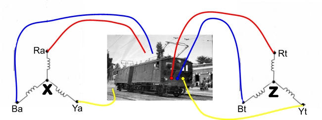
DIAGRAM
Consider the star-connected system. X and Z are on the neutral points of the alternator (in the generator building) and train motor (inside the train engine) respectively. In static systems each of these would be earthed through a high impedance, and provided the currents in the three phases are balanced they would stay at earth potential.
If, in the railway system, Ya and Yt are connected by the earthed rails and the connections at X and Z are left earthed, then the yelllow-phase voltage is short circuited. But if X and Z are allowed to float , the yellow phase voltage from the alternator is able to develop in the system, since the voltage at X and Z is no longer tied to earth.
For example, suppose the voltage at Ya is rising to a positive peak. Since Ya is tied to earth, the result will be a drop in voltage at X. That drop will combine with the voltages in the red and blue phases, so that it will appear at Ra and Ba.
Accordingly, the voltages at Rt and Bt will fall, and that will be passed to the neutral point Z, on the train, minus, of course, any drop in potential due to the resistance of the network. The overall effect is that Yt will become positive with respect to Z, even though it remains tied to earth potential. The same argument applies for the negative half-cycles, although the neutral points will then become positive with respect to earth.
This argument applies equally if a delta connection is used, although the explanation is a bit more complex as the voltages in two phases are involved at any time.
Best regards, Dick
Series I
Apart from the loading limits described above, the weight per axle was limited to 3 tons. The electric engines met this constraint but individual engines did not have enough power. So they were designed to work in coupled pairs. One other requirement was to have swift acceleration. This is an aspect that electric motors possess as anyone who has travelled on a trollybus will know.
The electric parts of engines were built by the Swiss firm Brown Boveri et Cie and the mechanical parts by the Ateliers Suisse pour la construction de wagons. The first engines arrived in 1910 and two more in 1924. They ran at 6KV 25Hz. The windings were split giving two fixed speeds of 25 or 12.5 kph. Like many Swiss engines, the current drawn reduced as speed reached its defined level. Above this speed, power was fed back into the system although I suspect that engine braking was the primary purpose of this.
The engines were taken out of service in 1966 when the electric system was closed. There were no other systems like this on RENFE so the engines were scrapped except for No 3 which was preserved in Madrid Railway Museum after a sixty year life.
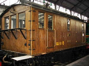
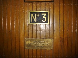
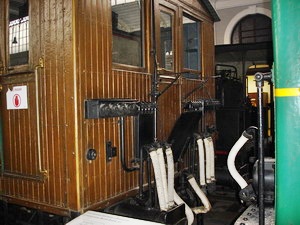
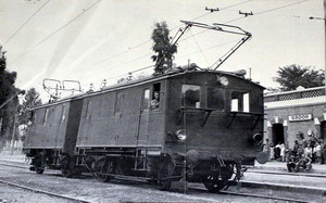
The first three pictures above show No 3 at the Madrid Railway Museum. On the left is the front of the engine, in the centre the number plate and on the right the rear, showing the coupling cables. The final picture shows No 4 and another unit at Gador Station.
Series II

These were delivered at the end of the 1950’s to pull passenger lines. The original engines still pulled freight trains. They were from the Swiss firm Sécheron (Picture attached) who delivered four Bo-Bo 1,300 hp engines numbered 21-24. This, however was the Franco era when everything had to be Spanish. I am sure that I remember that even Coca Cola had to be Spanish. It was reported that some parts were even smuggled into Spain to beat the restrictions! The result was that, for example, the motors were built in Bilbao and calibrated in Switzerland. Roger Kaller a Swiss engineer from Sécheron visited Almería for the proving trials. He reported that the trials were a disaster. These engines, like their predecessors, had two fixed speeds, this time 25 and 50kph. When they tried to run at the higher speed, everything went wrong. The pantographs fell apart and wore out, while the generator blew its trip switches. On the steep slopes, the system failed, even at 25kph. On top of this, the motors overheated.
Kaller abandoned his attempts and went home. However this is not the end of the sad saga. Later on the engines were put into service, with strict limitations. The spare collectors from series 1-7 were fitted. These worked fairly well although the engines only ever reached 50 kph when they were running solo. Their operating life was short however, for in 1966 with the coming of diesels, they were taken out of service.
Series III
These engines, 3000VDC,were of Japanese Mitsubishi design, arriving in 1989. Their most characteristic features were the use of two single-motor bogies and the low traction links that delivered more traction and less slippage to the wheels. They had a strong rheostatic brake to maintain a constant velocity on long descents. The numbers at Almeria changed over time as units were deployed by RENFE to where they were needed, but some remained until the end of mining in 1996. They were much more powerful, could reach 80kph and were not fixed as to speed.
©Copyright Don Gaunt
Click here to go to the Faydon.com Home Page